This project got underway in my spare time at the end of December 2020. It is the Medical Lift, ChamberLift 2000, from Lift Aid, Inc., by Guido Capaldi. This lift was provided by the Masonic organization Knights Templar. To operate the lift there are three equivalent switches to operate depending on which switch is more convenient. Two rockers that rock up and down and are at rest in the middle position while off. Meaning normally off in the middle, and momentary-on when held up for lifting or held down for lowering. These two rockers are located at the bottom of each of the two metal handles on either side of the hoist assembly. The third switch is an optional, wired, handheld remote, that plugs into an RJ-11 type connector on this PCB. The PCB, the RJ-11 connector and the other PCB components for user interaction are mounted to the metal bezel which has holes to allow the intended components to be offered to the user.
The symptom of the failure was when operating any of three switches to make the motor lift or lower, the spool apparently operates properly lifting, but is intermittent on down, or lowering. So lifting can take a few seconds as is normal, and lowering can take many attempts over several minutes, rendering it mostly useless. It seemed like voltage or capacitance build up, then failure of a component to either open or close, then the cycle repeats. The battery charge level LEDs work, and the green charging LED works. If you scroll down to the bottom here under Documentation, you can click on the component photo for C5 and see it was blown. Since the first day of visual inspection I had wondered if this was the only problem and while determining specifications for several spare parts in addition to C5, and then waiting for the shipment, I worked on the schematic in Autodesk Eagle in case it was going to get difficult.
The C5 replacement arrived, and only having an analog Ohmmeter and a 9 Volt battery, I compared tests of the visually bad C5 to the replacement C5 and they looked the same every test. I was flummoxed, and not being at the client site, I decided to keep looking for more obvious intermittencies in other components that I could prove. I was thinking the failing component most likely would have to have a twin component, meaning one for lifting and one for lowering, and this category of components included C5. In my spare time over many days, I removed and tested Power MOSFETs, transistors, resistors, and capacitors and found them all to be apparently good. So over time, I made about three separate orders, each for a few more potential part replacements from digikey.com, I finally made arrangements with the client to take my soldering tools to the client site and replace one component at a time until it worked. When I set up at the client's site, the first component I replaced was C5 ...and VOILA!! ...it was fixed! Now I'm shopping for a quality bench digital multimeter like possibly a Fluke, Klein, B&K, etc., that will give me the ability to measure Farads, a diode mode, and increased sensitivity. It may prove pricey but will be a real time-saver.
Close up of hoist housing showing metal frame in backgrouind.
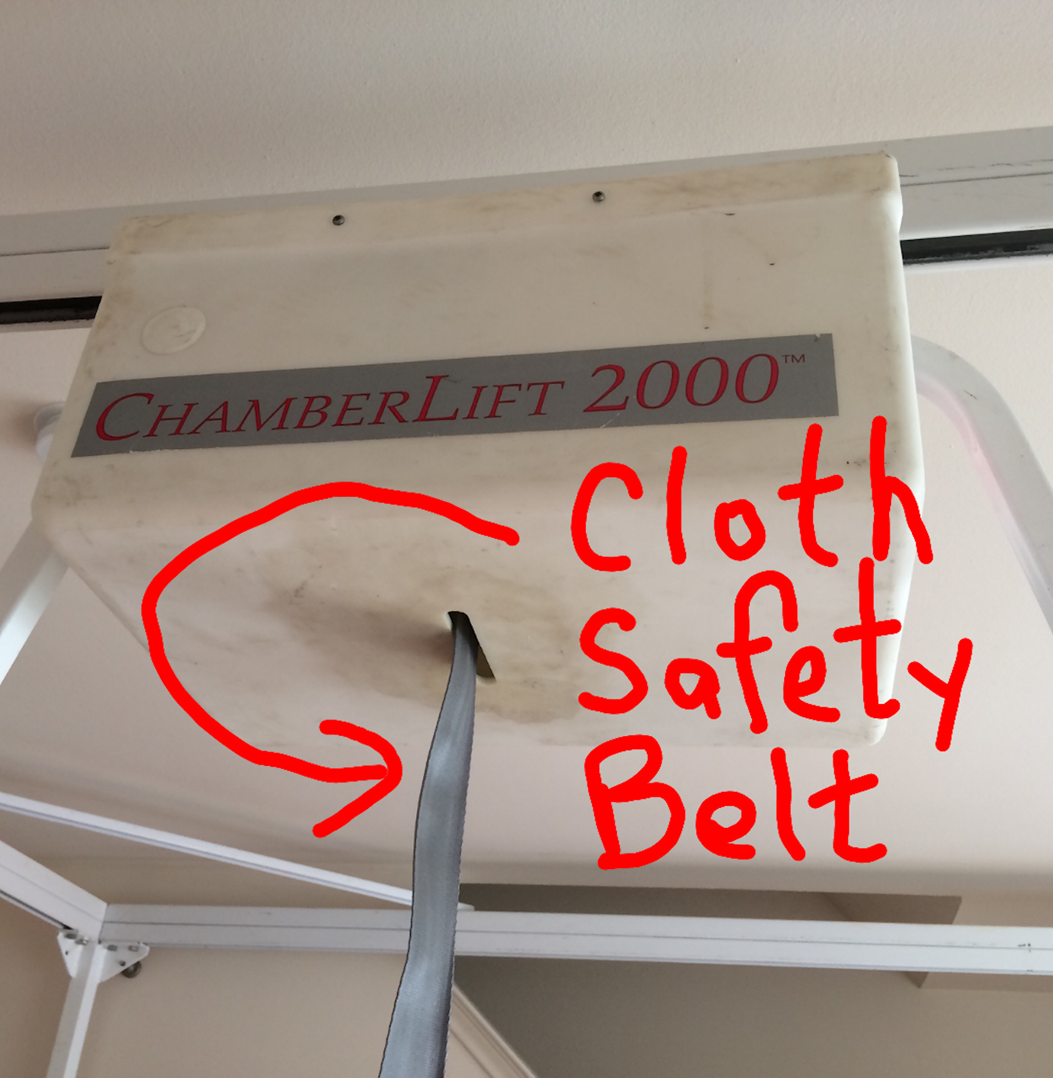
Showing the cloth belt that coils and uncoils from the hoist spool to raise and lower patient.
Close up of one of the two square tube handles that each have a rocker switch to lower and raise patient.
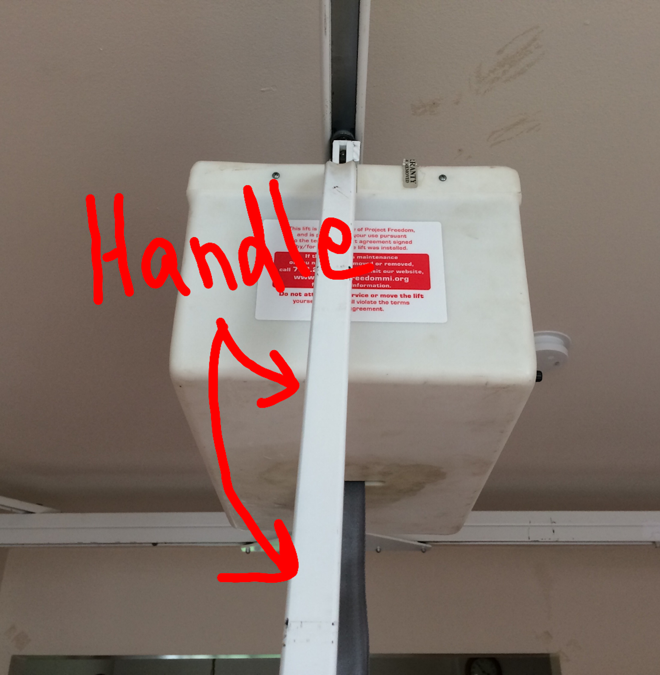
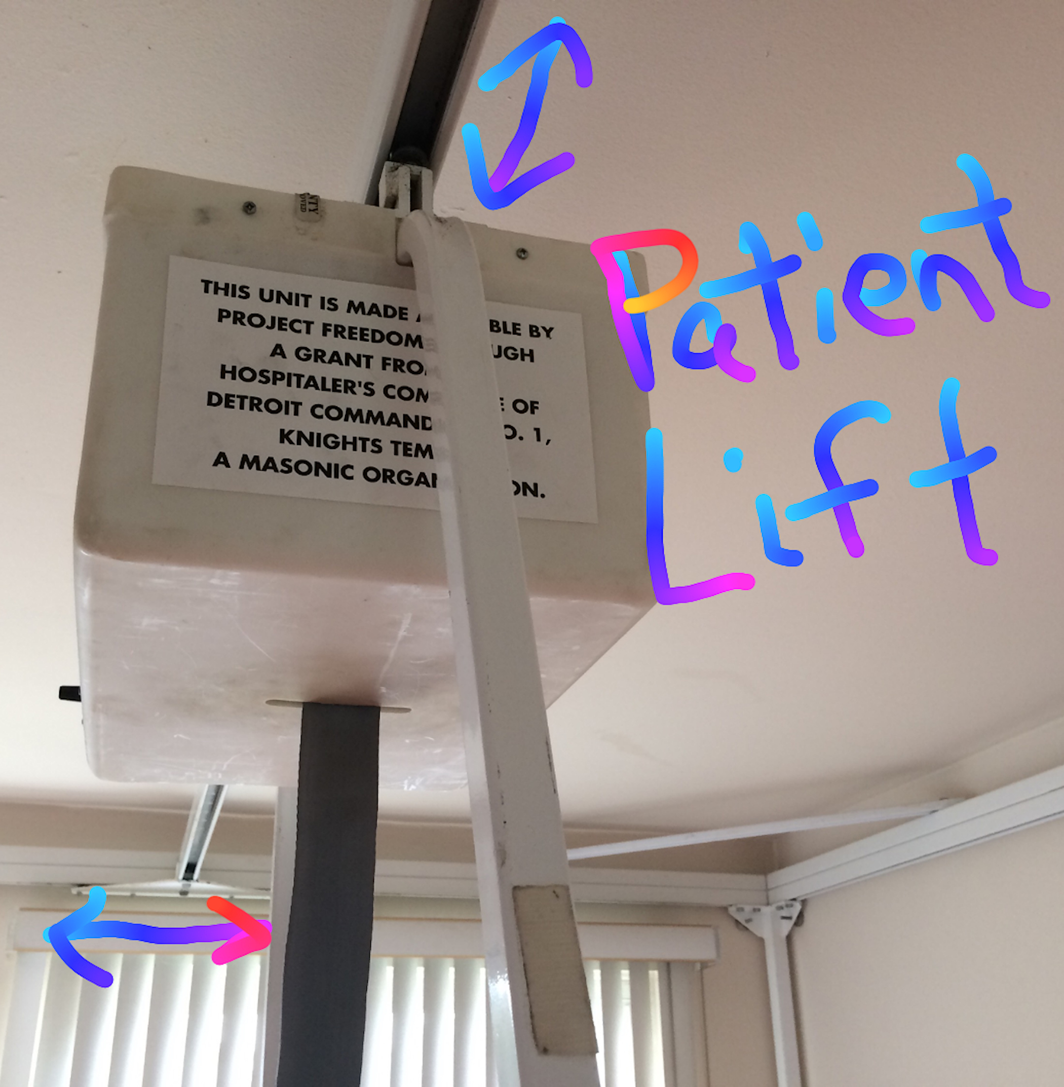
Photo of hoist assembly highlighting location of PCB control panel installed.
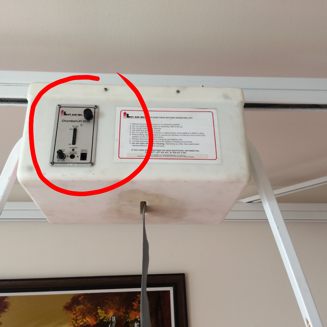
Photo showing hoist housing open and highlighting major components.
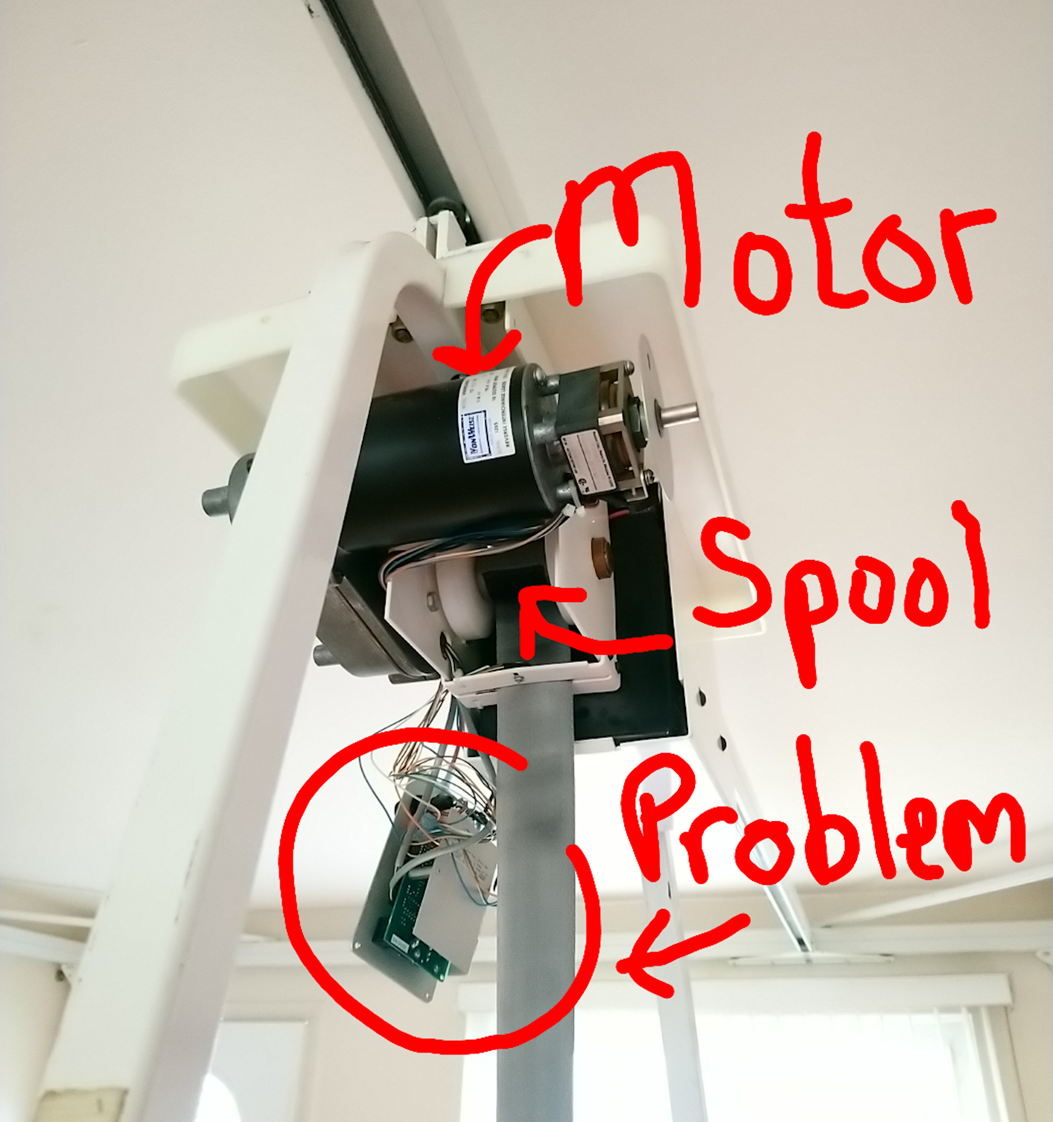
Photo showing front of PCB control panel assembly by itself removed from hoist assembly.
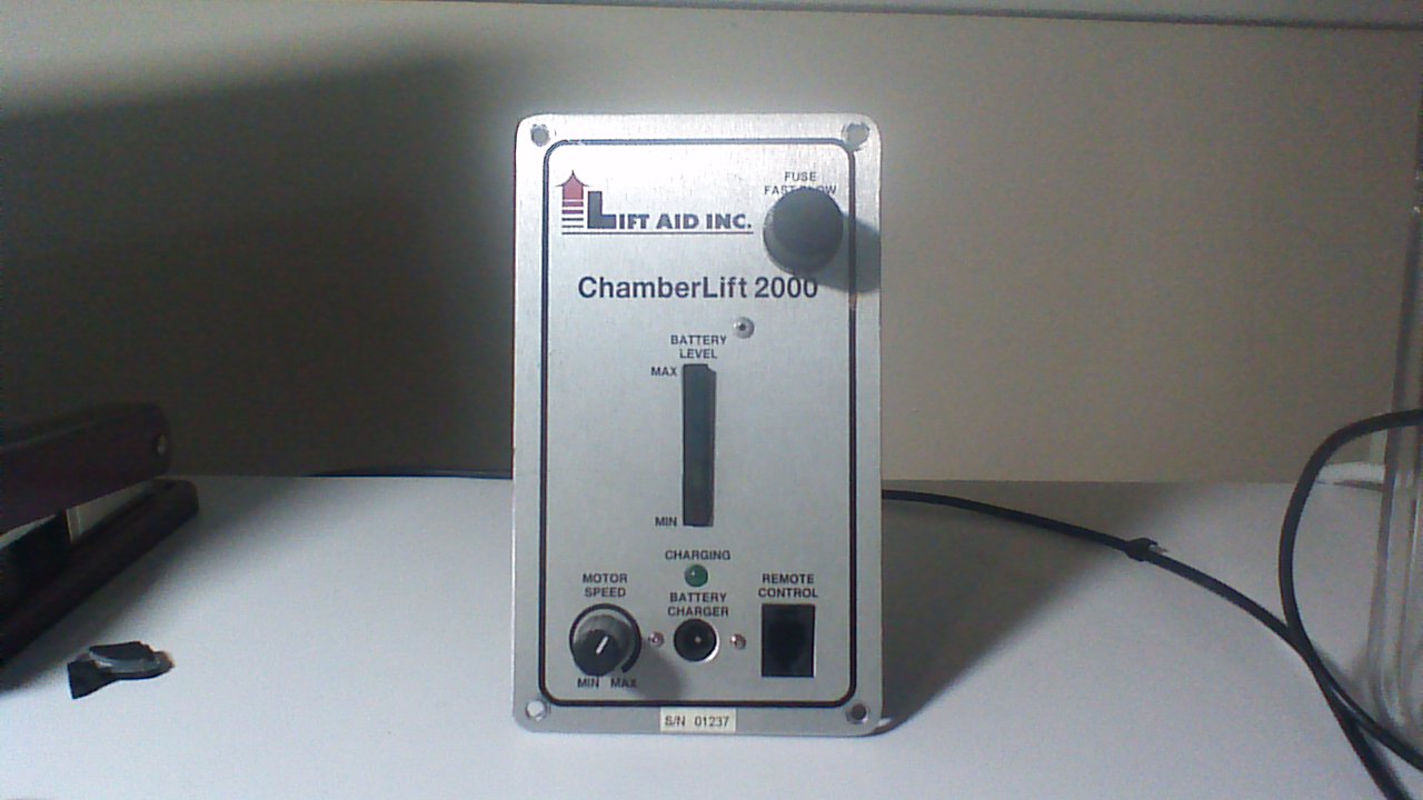
Photo showing rear of PCB control panel assembly by itself removed from hoist assembly.
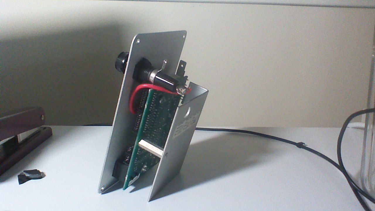
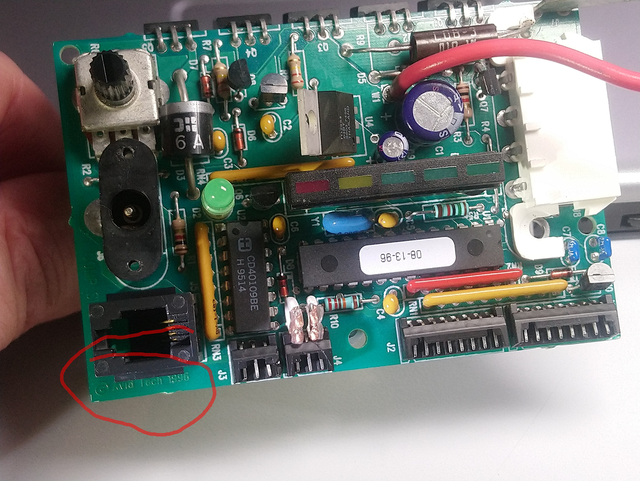
Photo showing PCB component side with red circle around manufacturer AVID which is now AVNET.
22 second Video of repaired ChamberLift 2000 with a new C5 capacitor. This is the same video posted to my Instagram account "@wigglemylegs" where you may also view other small projects.
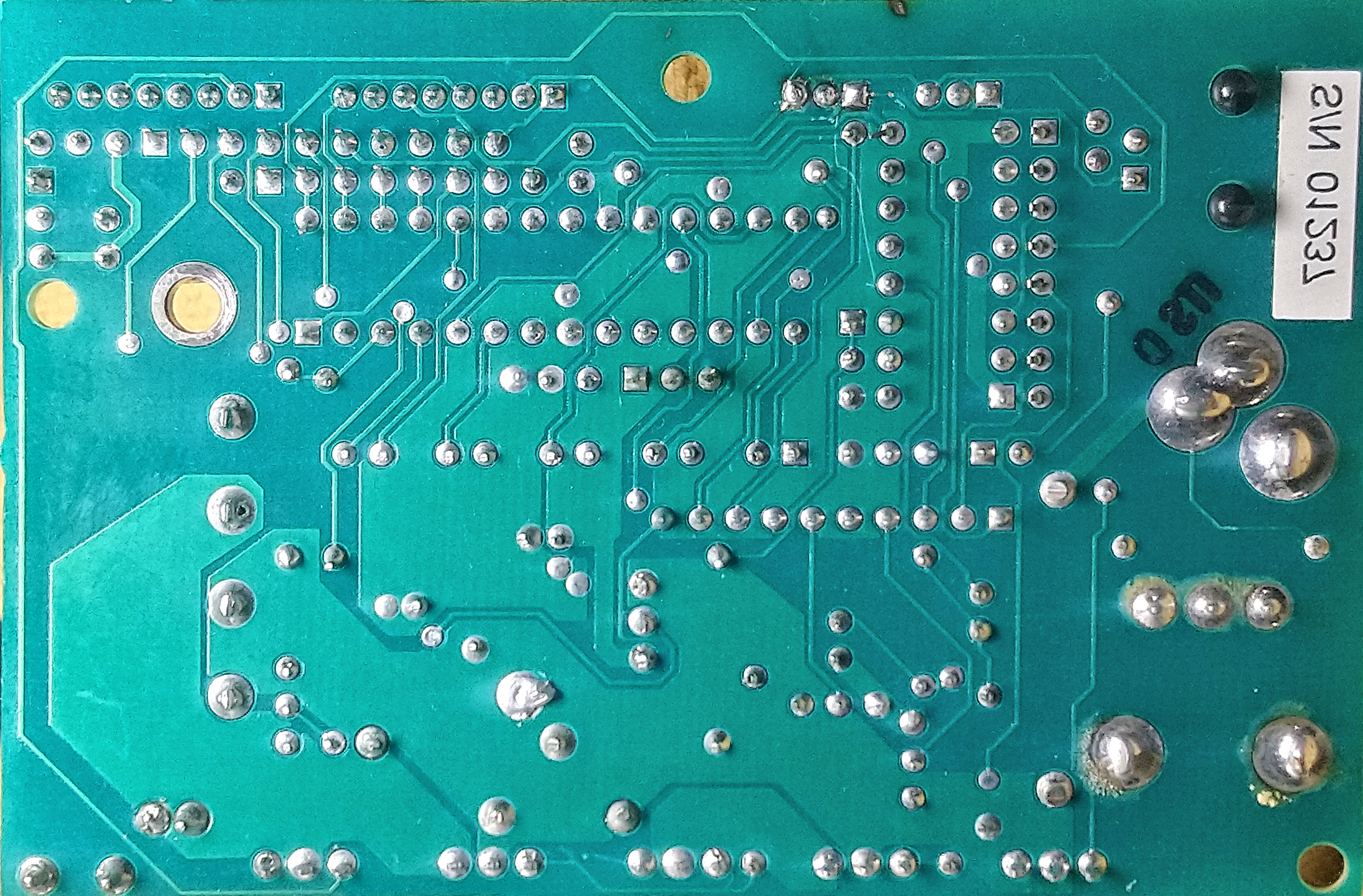
300dpi photo of PCB solder side.
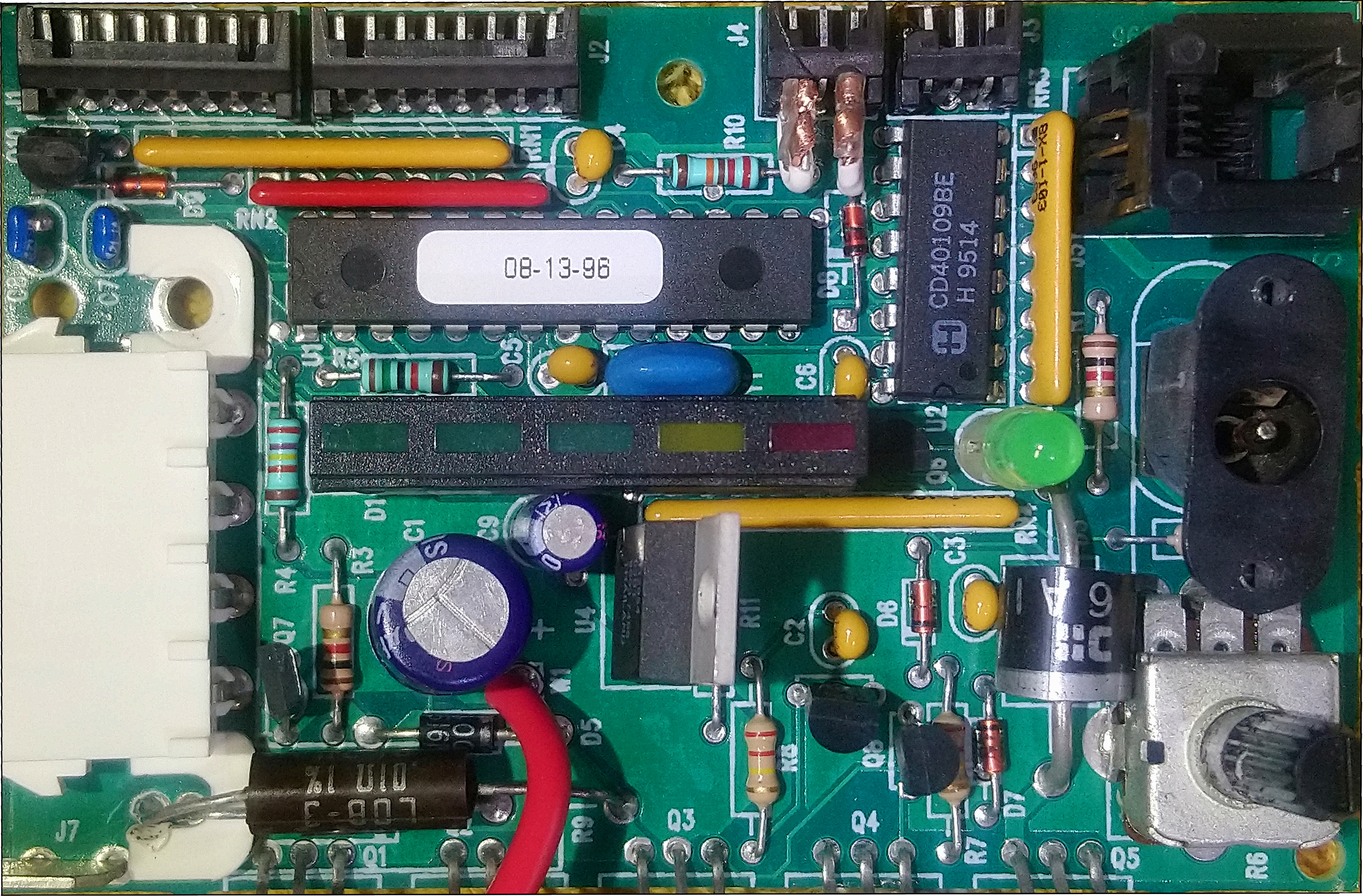
300dpi photo of PCB component side.
Here below is a link to download the 20-25 MB Excel spreadsheet of the BOM. The downloaded Excel file arrives in "Protected View" so after downloading, if you want to view the photos in column 1, you must "Enable Editing" by clicking the "Enable Editing" button in the yellow notification banner, or under File / Options / Advanced. If you prefer to keep the Excel file in "Protected View," the photos can be viewed in the browser using the direct links here below under "Original Component Photos." The file is 20-25 MB because it contains about 51 photos. Somehow the dimensions of the photo windows are not remaining set the way I set them. The photos are inserted into the cell as a background fill pattern for a "Note" in the cell. If the pictures are not completely visible, right-click the cell, select "Edit Note" (older Excel might show Edit Comment), you'll see a white box window for text that is blank and it has sizing handles. Click and drag the sizing handles to reveal the missing part of the photo. You'll see when you click the window sizing handle the white text box disappears revealing the photo.
Original Component Photos
Component_C1
Component_C2
Component_C3
Component_C4
Component_C5
Component_C6
Component_C7
Component_C8
Component_C9
Component_D1
Component_D2
Component_D3
Component_D4
Component_D5
Component_D6
Component_D7
Component_D8
Component_D9
Components_J1&J2&J3&J4
Component_Q1
Component_Q2
Component_Q3
Component_Q4
Component_Q5
Component_Q6
Component_Q7
Component_Q8
Component_Q9
Component_Q10
Component_R1
Component_R2
Component_R3
Component_R4
Component_R5
Component_R6
Component_R7
Component_R8
Component_R9
Component_R10
Component_R11
Component_RN1
Component_RN2
Component_RN3
Component_RN4
Component_U1
Component_U2
Component_U4
Component_Y1