Thermador Model GPS366 Gas Stove All Restored in 2018
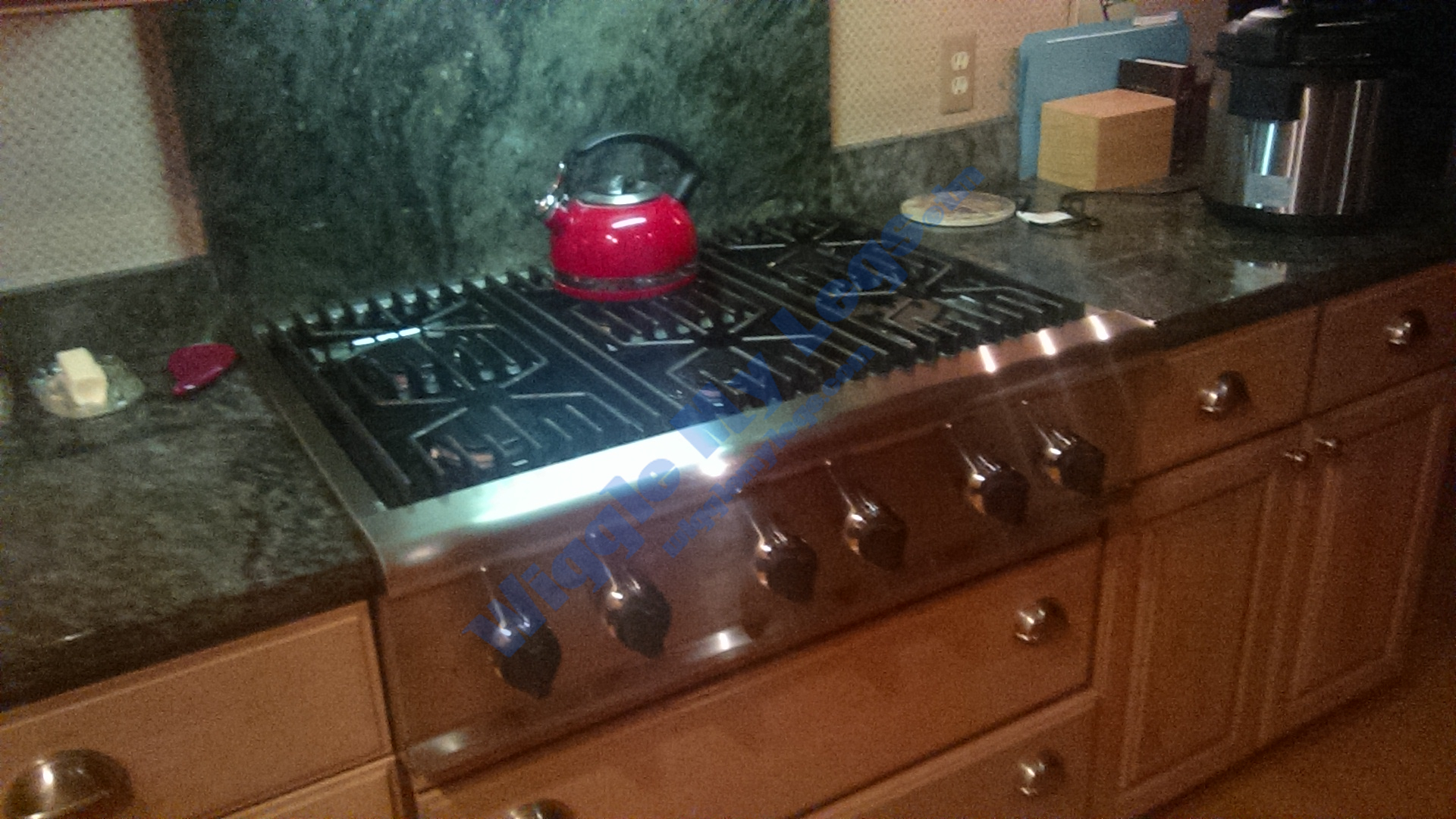
The photo above is the restored Thermador model GPS366 S/00 gas stove. Prior to the restoration, the two left burners were no longer lighting. Those two left burners are controlled electronically to turn the gas on and off at different intervals for varying levels of simmer. It seemed obvious the electronic control circuitry had been impaled by power surges during thunderstorms just prior to those two burners quitting. Once the repair was well underway, I realized I should be taking more video and stills for this URL, but I got another chance. Now in May of 2020, almost two years after the original repair shown here, the day I was organizing these old photos and videos of this Thermador repair in order to upload them to the Wiggle My Legs URL, the front of the two left two burners went out. Unbelievable coincidence, but an opportunity to get more photos and video. After it was repaired in 2018 we protected it with a surge protector. We also treated it with a Black & Decker belt sander, some 3M scratch pads, some Dico buffers with Dico polish on the spill trays with the aid of a Makita drill, and some Rust-o-leum flat black appliance paint for the sunken logo and burner indicators and the stove gained a brand new life. Later in May of 2020, the front left burner went out, which was simply due to age and wear of the potentiometer for the left front burner. A year or so prior to this entire restoration, I had already replaced the potentiometer for the left rear burner. So now in May, 2020, 2 years after the restoration, the other finally went out also. I've included some one-handed video of testing and assembly here at the end.
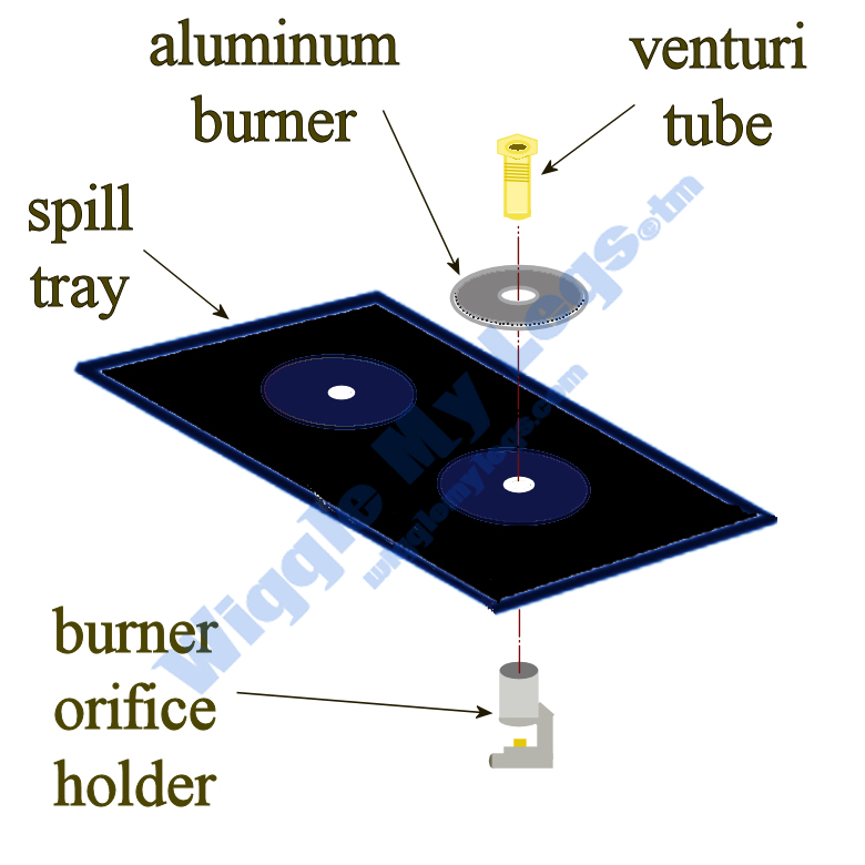
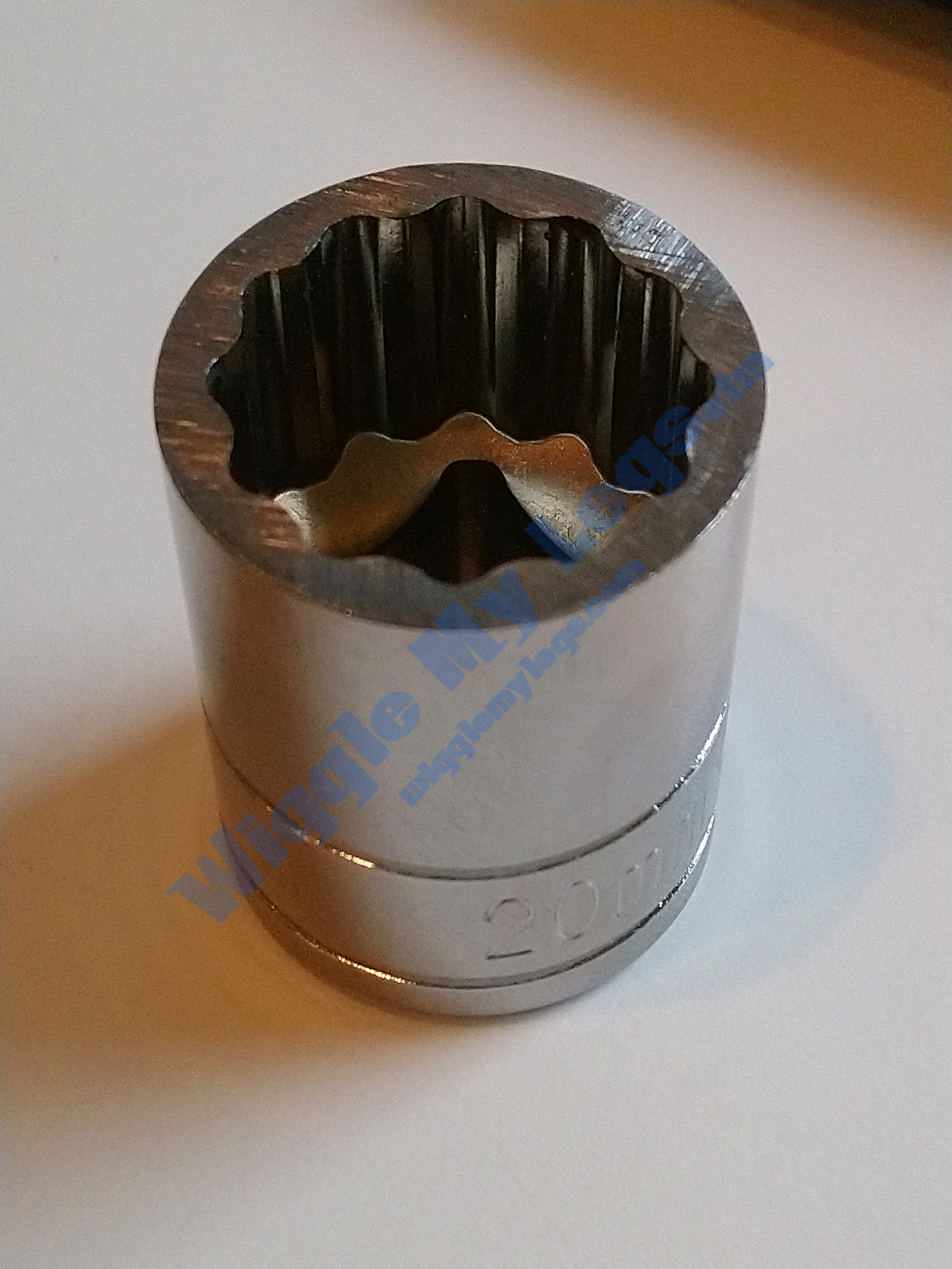
After lifting off the burner caps, the front three venturi tubes (see blow up diamgram below) were very difficult to remove. This was due to years of using mostly the front burners, which causes the venturi brass to fuse with the aluminum burner orifice holder. Also, the height of the hex fitting of the venturi is such a low profile it is hard to get a grip without destroying the aluminum burner. I tried using a socket wrench, but the socket lip has a rounded edge preventing the opening of the socket from firmly gripping the shallow hex head when a little torque is applied. As you see in the photo below, this problem made me get the grinder out and grind my socket opening down by a little less than a quarter inch. This removed the slightly rounded lip at the opening of the socket, allowing six corners of the socket to make completely flush contact with all six corners of the shallow hex head for a snug fit. The back three venturis were fairly easy to remove as those burners were not used often. Of the three front venturis that were stuck, one was freed with this socket and a whole bunch of torque. Another one would not let go of the burner orifice beneath the spill tray, so I turned with the socket until I twisted off the gas supply pipe under the burner orifice and it broke off. After that lesson, the third stuck venturi still wasn't listening and I decided to grind the venturi hex fitting off the top which releases the aluminum burner to be lifted off the spill tray, which allows removal of the spill tray. Of course, when the spill tray is removed I had a burner orifice holder with the remains of the venuturi fused into it, which was uncoupled from the gas supply and replaced. Fortunately, appliance repair companies such as our local Mastertech, and of course RepairClinic.com are always there for me during these rough moments and for this project Repair Clinic is only a short drive away to pick up parts that seem to always be in stock.
Here is the 20mm socket that I ground off to make flush contact with the shallow hex fitting.
While removing the spill trays it was a little difficult to keep the rubber sealing strips under the spill trays intact due to it's binding with years of cooked spilled food making it rip in some locations. Here below is a quick video showing the remnants of the rubber seals with two of the three spill trays removed. I used it to show the application to rubber vendors.
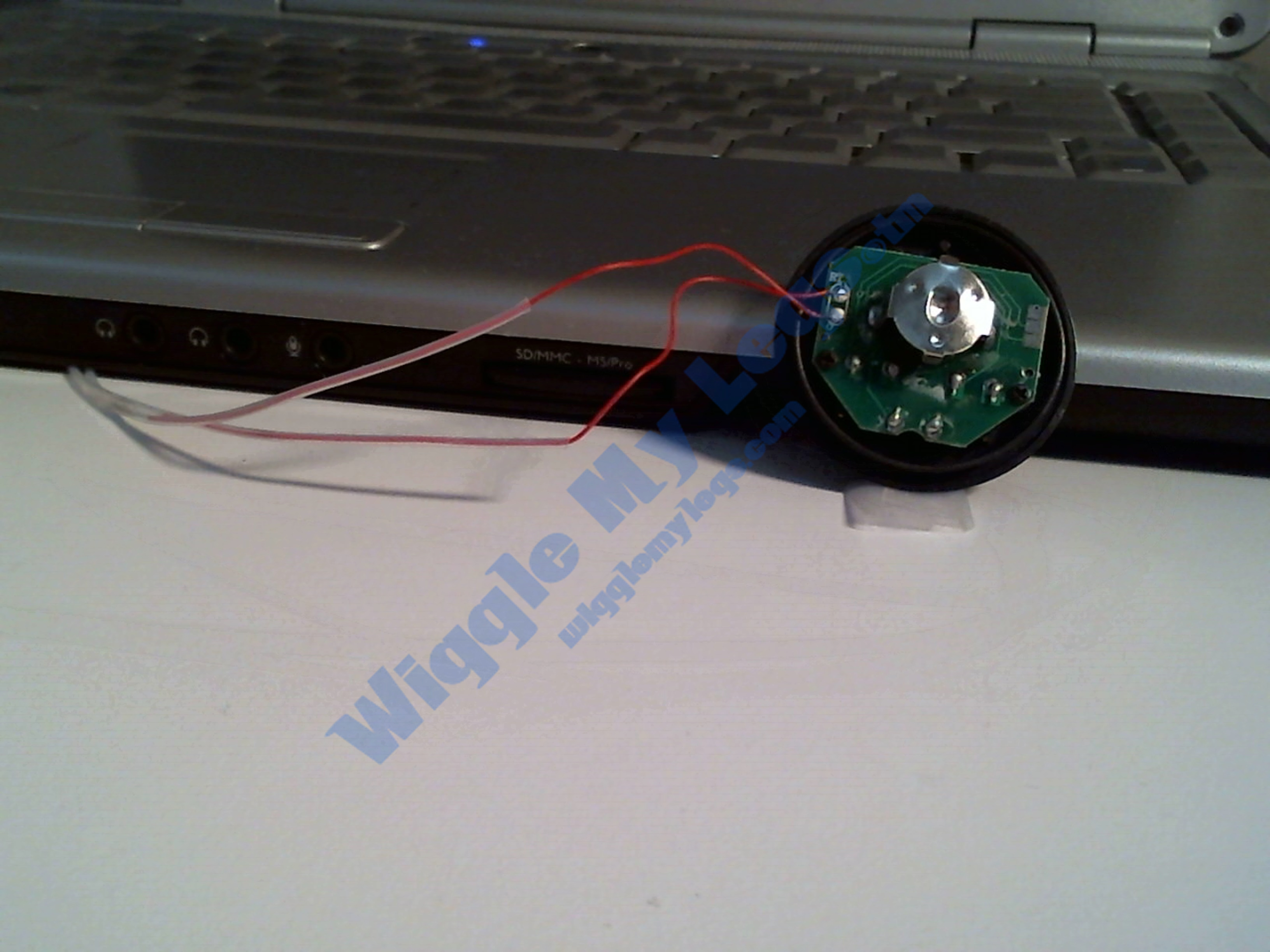
The photo below is the thermocouple I used to test the temperature under the rims of the spill trays at the location of the rubber seals. It is a meat thermometer with the metal sheath probe removed to expose the thermocouple wiring, shown here leaning on my laptop. I could then insert the thermocouple under the spill tray edge where the rubber seals are located to measure the temperature, and it would hang below to display the temperature. If I recall, I could get temperatures as high as 380 degrees F after 30 minutes.
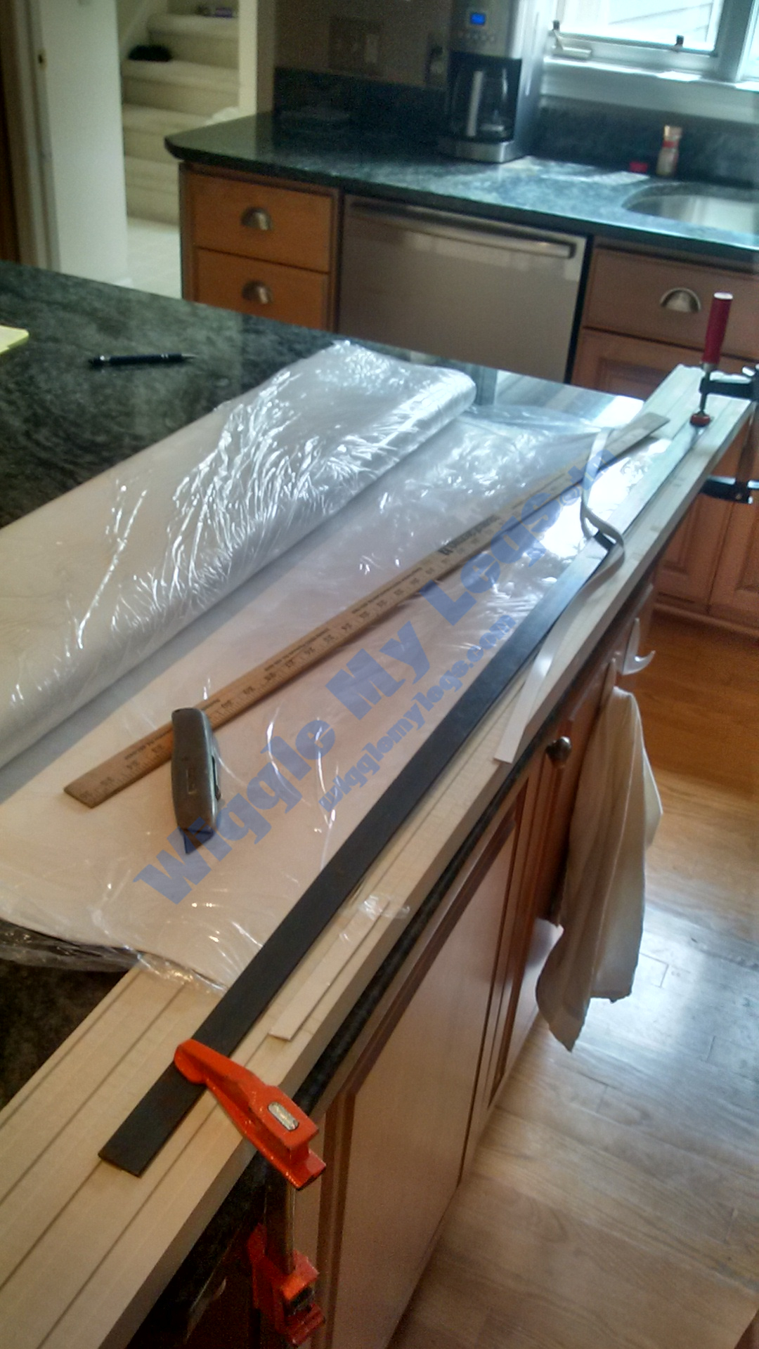
Although the next photo is out of sequence and from final assembly, it shows how Rubbercal in California came through with some food grade (FDA approved for use around food with specifications under "Documentation" here below) rubber sheeting rated at 450 degrees F. I had to buy a great deal of it so if anyone wants some I'd be glad to sell. This photo is after PCB repairs were complete and during stove reassembly showing a black metal straight edge clamped onto the new rubber sheet to slice off the new half inch wide strips. One of the new strips is strewn across the black straight edge over to the yard stick. I contacted RubberCal April 15, 2020 while composing this text and they still have the item number in their system, but their supplier quit making it so none is available.
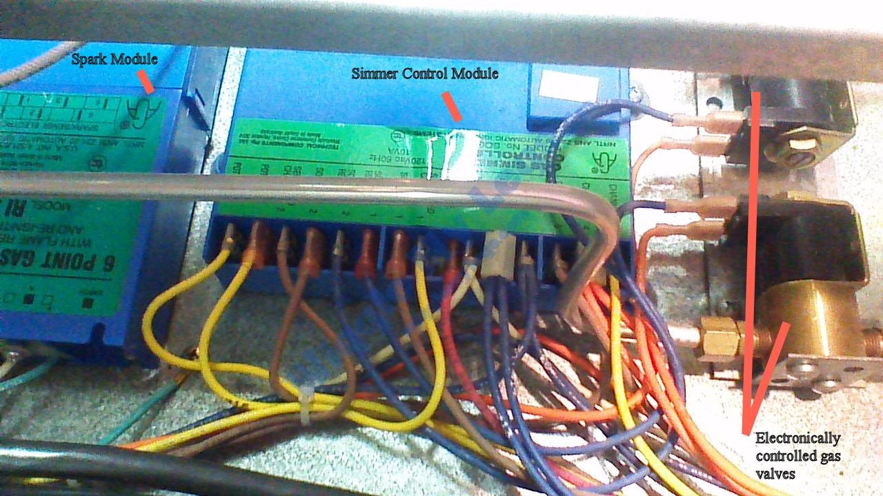
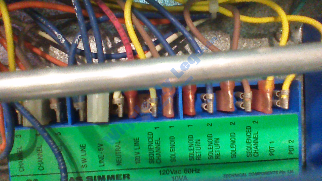
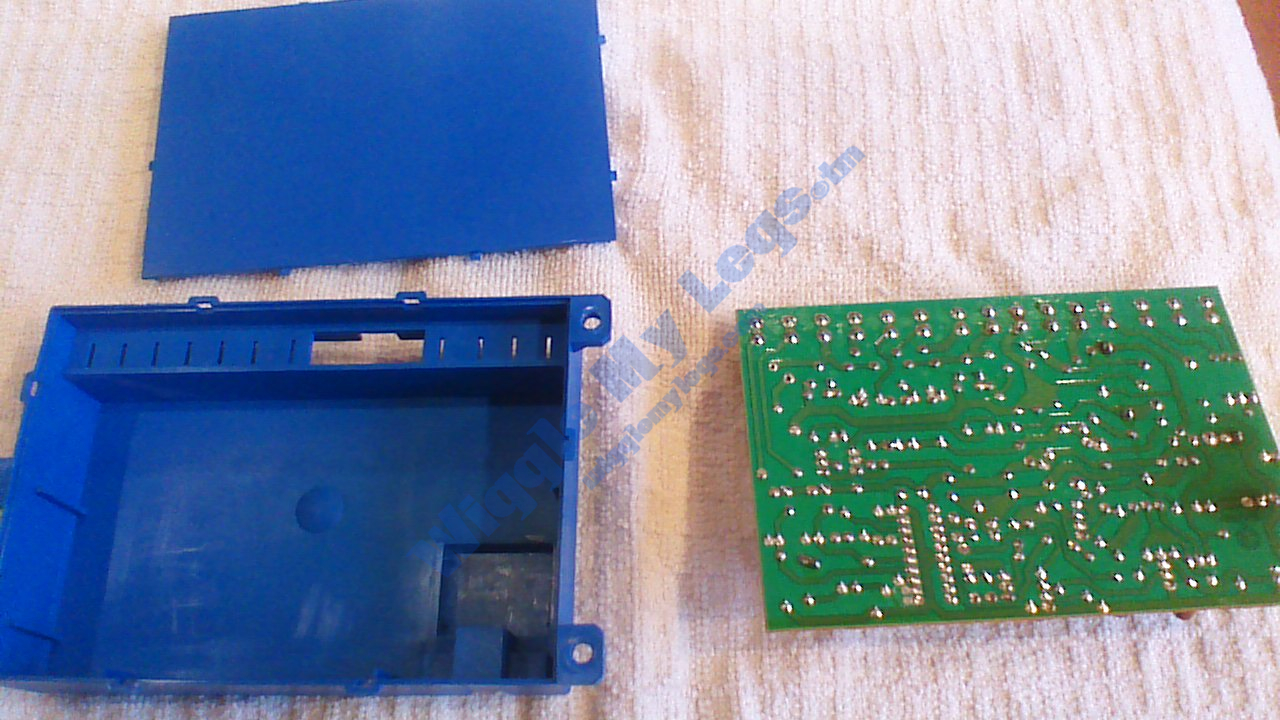
The next step was to remove the two blue plastic boxes called the Simmer Control Module and the Reignition Spark Module and open them for visual inspection. The two pictures below are before removing the two blue plastic modules in order to document the wiring for reassembly.
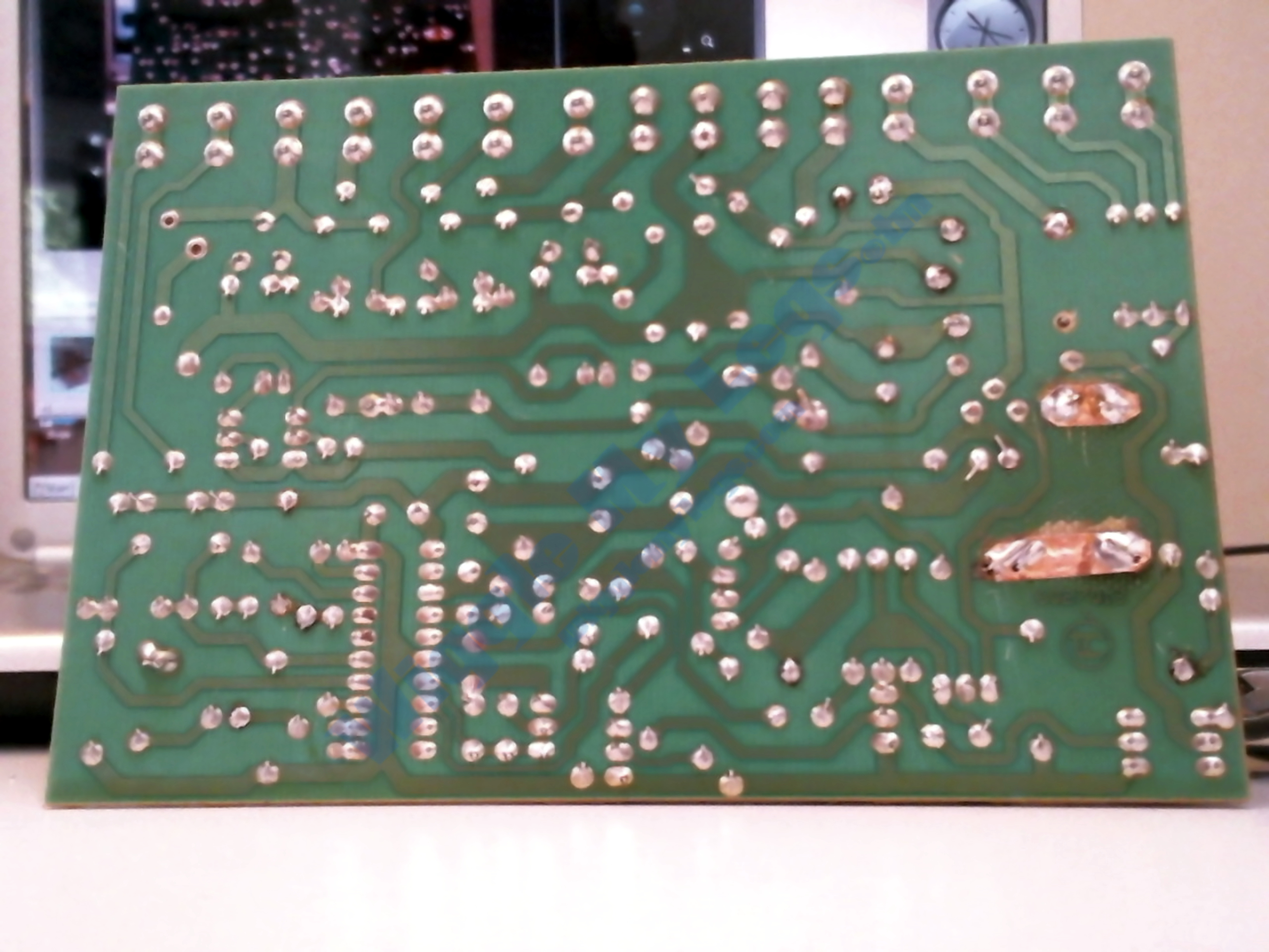
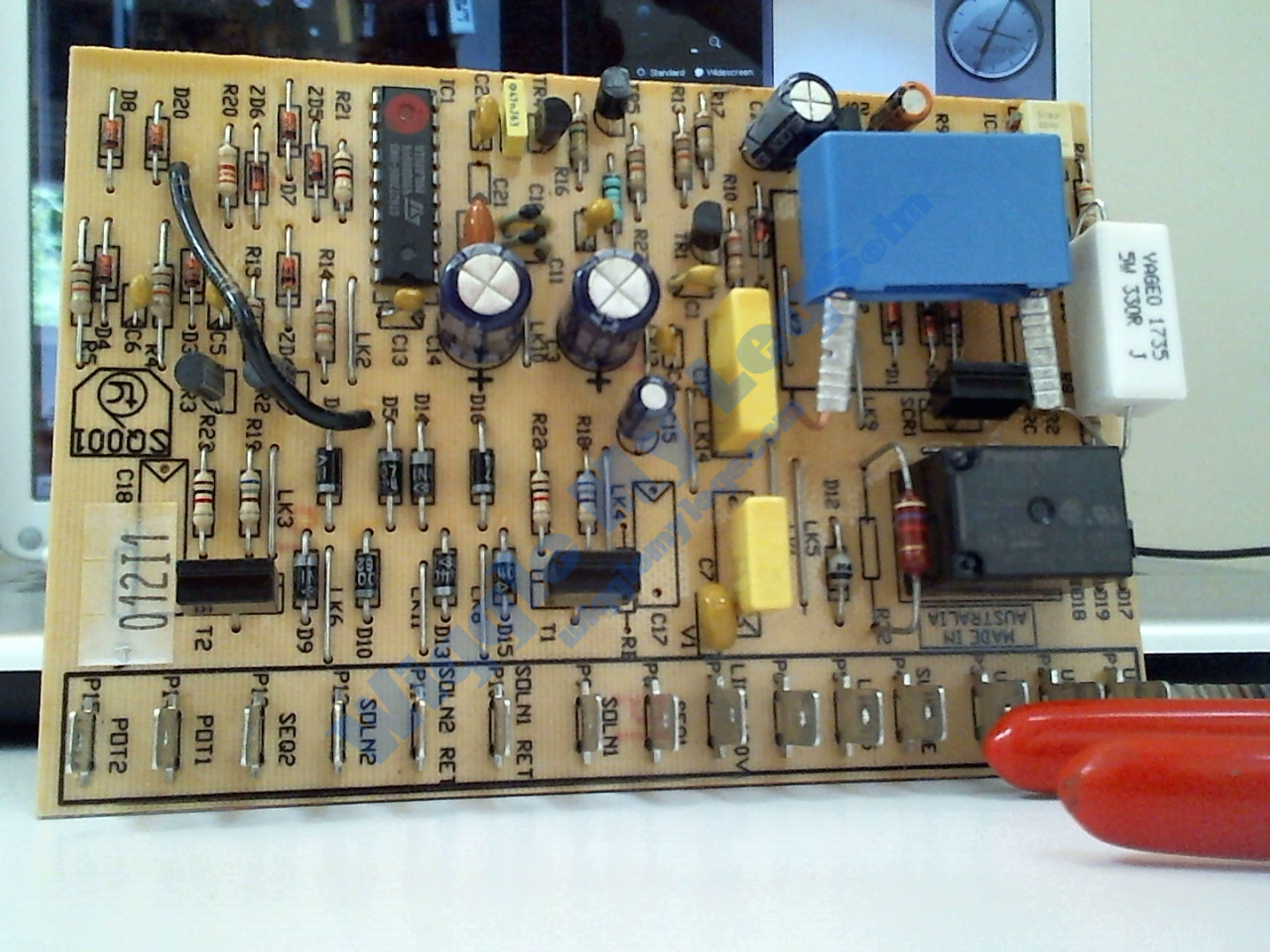
After removing the Simmer Control Module and opening it to inspect the printed circuit board (PCB), it is easy to see the scorch marks near the big resistor R2 and the large capacitor C2. There was also heat evidence at some of the terminal pins. In the first photo R2 and C2 are highlighted on the left end of the PCB and the second photo the PCB is flipped so the scorch marks are on the right. At the time of the repair in June of 2018, the Simmer Control Module was no longer available as a spare part from Thermador and was hundreds of dollars on the Net. I removed R2 and C2 and realized I needed to write down the circuit and check related components and test. I hoped to do a complete proven schematic, but eventually when the stove started to function, time management intervened and I stopped short of complete and proven documentation. Yet if someone were doing this repair the schematic would be helpful. UPDATE: A kind person that wants to remain nameless, and who has a simmer control module, and who happens to be an experienced engineer, put together the schematic in Kicad and you can download it here as a PDF.

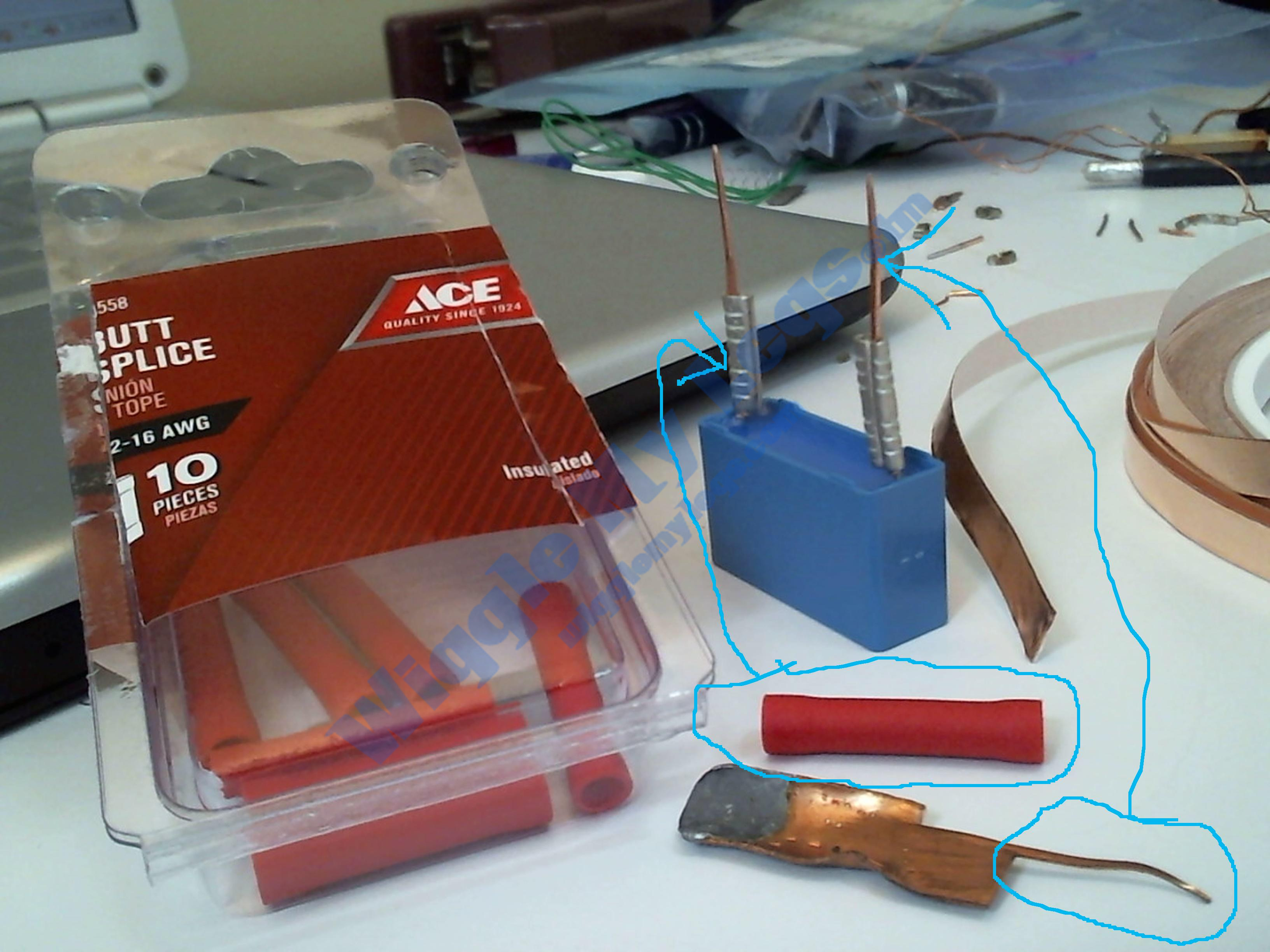
The new PCB replacement components were purchased from DigiKey.com out of Minnesota. They were incredibly patient and helpful. The lead time was a few weeks for a more closely matched R2 resistor, so we opted for the closest resistor in stock. Other companies also were helpful such as Jameco, and Summit Electronics, while Eaton was absolutely awesome when researching resistor R2. The replacement for C2 had great electrical specifications but it's leads were too short for this application which caused me to mechanically crimp on some extensions as you see in the pictures below. The ACE Hardware copper sheet metal was from an old project and I used shears to slice off the new leads you see crimped onto C2. The ACE Hardware 22-16 AWG Butt Splices had their red plastic covers stripped off because I was only using the metal tubes inside. Also, the coil of 3M copper foil tape purchased from ULINE can also be seen on the right, which was used to replace the lifted traces on the PCB's solder side.
The repaired PCB is shown here below. Since I had it all open, I decided to replace more components than technically required. If I recall I needed about 3-4 parts, such as R2 and C2, but since I ordered more I put in a total of about 12 new components such as capacitors, diodes, and the relay and optoisolator. At R2 and C2, the original traces had lifted off the solder side and were replaced with 3M copper foil tape which had to be glued to the board to prevent the foil tape from being peeled off the PCB by the physical shock of applied current to the relatively large mass components soldered to the tape. I used PCFix high heat epoxy putty. On the component side you can see the newly crimped on leads for C2 will fit well enough to allow the unit back into the blue plastic box easily.
As mentioned in the opening, a few days ago in May of 2020, I was cleaning up some files to upload this repair segment to wigglemylegs.com and the left front burner went out that day. I finally remembered to turn on the camera and recorded some diagnosis and reassemnbly. Here is a quick video of me trying to to left hand the camera and right hand the diagnosis and reassembly. My trusty Radio Shack multimeter shows the output from the Simmer Control Module to the front burner is low voltage. In May of 2020, this new left front burner failure turned out to be simply the potentiometer wearing out. A couple years or so prior to this entire restoration, I had already replaced the potentiometer for the left REAR burner. So this one now came due.
Here below are the circuit traced diagram of the Simmer Control Module PCB, the photos of individual PCB components, and also supplemental PDF documents for certain PCB components. There is also an Excel spreadsheet that was going to be a complete Bill of Materials for the entire PCB with photos of individual components in comments for each component's cell. Once the spreadsheet is open, enable editing. You'll see there are red markers in the cells which have photos, and if editing has been enabled, hovering over a cell with a red marker should bring up the related photo.
Original Component Photos
Component PCBSideA
Component PCBSideB
Component PCBAfterSideA
Component PCBAfterSideB
Component C1
Component C2
Component C3
Component C4
Component C5
Component C6
Component C7
Component C8
Component C9
Component C10&C11
Component C12
Component C13
Component C14
Component C15
Component C16
Component C19
Component C20
Component D1
Component D2
Component D3
Component D4
Component D5
Component D6
Component D7
Component D8
Component D9
Component D10
Component D11
Component D12
Component D12Up
Component D13
Component D14
Component D15
Component D16
Component D17
Component D18
Component D19
Component D20
Component IC1
Component IC3
Component R1
Component R2
Component R3
Components R4&R5
Components R6&R7&R8&R9
Component R10
Components R11&R12
Component R13
Component R14&R15
Component R16
Component R17
Component R18
Component R19
Components R20&R21
Component R22
Component R23
Component R27
Component R32
Component Relay
Component RES1
Component SCR1
Component T1
Component T2
Component TR1
Component TR2&TR3
Component TR4
Component TR5
Component TR8
Component TR9
Component V1SideA
Component V1SideB
Component ZD1
Component ZD1Up
Component ZD2
Component ZD2Up
Component ZD3
Component ZD3Up
Component ZD4
Component ZD4Up
Component ZD5
Component ZD5Up
Component ZD6
Component ZD6Up
Click here,to download the spreadsheet of the above components with the above pictures embedded in the cell's comments, and specifications for some components. Once the spreadsheet is open, be sure to enable editing.
Documents below are related to the parts shown above.
IC3 by Motorola PDF. Click the little blue text link when you arrive at alldatasheet.com
RubberCal Rubber sheeting specifications PDF.
The new C2 capacitor by EPCOS PDF.
IC1 "ST62T20B6-HWD" by ST PDF.
Relay JS1 by Matsushita PDF.
Thermador Models GPS366S, GPS364GDS, GPS364GLS, GPS484GGS, GPS366GDS, GPS366GLS, GP24WKS Parts List